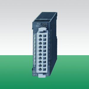
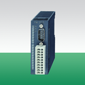
Counter module FM250 250-1BS00
| Назначение | Адресное пространство | Входы | Выходы |
|
Счетчик абсолютного энкодера Количество счетных каналов: 1 х SSI 100/300/600 кбит/с Физическая среда интерфейса RS-422 |
входы 4 байт выходы 4 байт параметры 6 байт |
0...2 шт, PNP 24 B/1 время задержки 0,5 мкс |
0...2 шт, PNP 24 B/1 ток нагрузки не более 1 А Деление по входам/выходам программно |
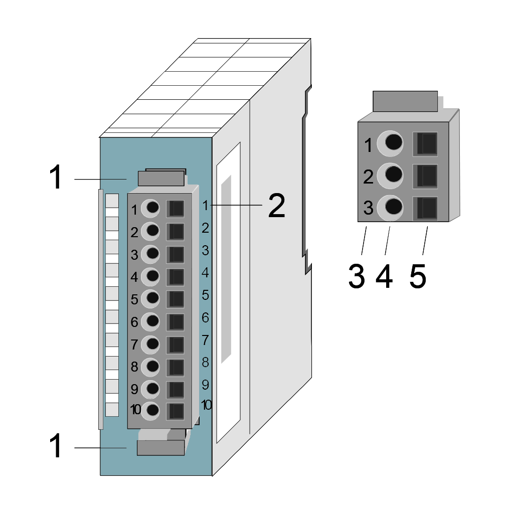
| Модуль FM | Описание | |
 |
|
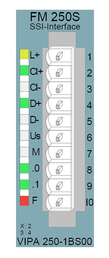
| Индикация состояния FM | Модуль FM | Назначение контактов |
|
|
L+ Наличие напряжения питания CI+ Тактовые импульсы передаются D+ Ввод данных .0 Вход / Выход 0 .1 Выход 1 F Ошибка / перегрузка
|
 |
|
Order no. |
250-1BS00 |
| Type | FM 250S |
General information |
|
| Note | - |
| Features | 1 SSI channel Direct power supply to the SSI transducer Baud rate: 100/300/600 kBit/s (default: 300 kBit/s) 2 configurable digital outputs, one may be used as hold input |
Current consumption/power loss |
|
| Current consumption from backplane bus | 120 mA |
| Power loss | 1 W |
Technical data digital inputs |
|
| Number of inputs | 2 |
| Cable length, shielded | 1000 m |
| Cable length, unshielded | 600 m |
| Rated load voltage | DC 24 V |
| Reverse polarity protection of rated load voltage |  |
| Current consumption from load voltage L+ (without load) | - |
| Rated value | - |
| Input voltage for signal "0" | Differential signal RS422 |
| Input voltage for signal "1" | Differential signal RS422 |
| Input voltage hysteresis | - |
| Frequency range | - |
| Input resistance | - |
| Input current for signal "1" | - |
| Connection of Two-Wire-BEROs possible | - |
| Max. permissible BERO quiescent current | - |
| Input delay of "0" to "1" | - |
| Input delay of "1" to "0" | - |
| Number of simultaneously utilizable inputs horizontal configuration | - |
| Number of simultaneously utilizable inputs vertical configuration | - |
| Input characteristic curve | - |
| Initial data size | 4 Byte |
Technical data digital outputs |
|
| Number of outputs | 2 |
| Cable length, shielded | 1000 m |
| Cable length, unshielded | 600 m |
| Rated load voltage | DC 24 V |
| Reverse polarity protection of rated load voltage | |
| Current consumption from load voltage L+ (without load) | 5 mA |
| Total current per group, horizontal configuration, 40°C | 2 A |
| Total current per group, horizontal configuration, 60°C | 2 A |
| Total current per group, vertical configuration | 2 A |
| Output voltage signal "1" at min. current | L+ (-0.8 V) |
| Output voltage signal "1" at max. current | L+ (-125 mV) |
| Output current at signal "1", rated value | 1 A |
| Output current, permitted range to 40°C | - |
| Output current, permitted range to 60°C | - |
| Output current at signal "0" max. (residual current) | - |
| Output delay of "0" to "1" | max. 100 µs |
| Output delay of "1" to "0" | max. 350 µs |
| Minimum load current | - |
| Lamp load | 5 W |
| Parallel switching of outputs for redundant control of a load | not possible |
| Parallel switching of outputs for increased power | not possible |
| Actuation of digital input | - |
| Switching frequency with resistive load | max. 1000 Hz |
| Switching frequency with inductive load | max. 0.5 Hz |
| Switching frequency on lamp load | max. 10 Hz |
| Internal limitation of inductive shut-off voltage | L+ (-52 V) |
| Short-circuit protection of output | yes, electronic |
| Trigger level | 1.8 A |
| Number of operating cycle of relay outputs | - |
| Switching capacity of contacts | - |
| Output data size | 4 Byte |
Status information, alarms, diagnostics |
|
| Status display | yes |
| Interrupts | no |
| Process alarm | no |
| Diagnostic interrupt | no |
| Diagnostic functions | no |
| Diagnostics information read-out | none |
| Supply voltage display | yes |
| Group error display | yes |
| Channel error display | none |
Isolation |
|
| Between channels | - |
| Between channels of groups to | - |
| Between channels and backplane bus | |
| Between channels and power supply | - |
| Max. potential difference between circuits | - |
| Max. potential difference between inputs (Ucm) | - |
| Max. potential difference between Mana and Mintern (Uiso) | - |
| Max. potential difference between inputs and Mana (Ucm) | - |
| Max. potential difference between inputs and Mintern (Uiso) | - |
| Max. potential difference between Mintern and outputs | - |
| Insulation tested with | DC 500 V |
Datasizes |
|
| Input bytes | 4 |
| Output bytes | 4 |
| Parameter bytes | 6 |
| Diagnostic bytes | 0 |
Housing |
|
| Material | PPE / PA 6.6 |
| Mounting | Profile rail 35 mm |
Mechanical data |
|
| Dimensions (WxHxD) | 25.4 mm x 76 mm x 78 mm |
| Weight | 100 g |
Environmental conditions |
|
| Operating temperature | 0 °C to 60 °C |
| Storage temperature | -25 °C to 70 °C |
Certifications |
|
| UL508 certification | yes |
| Order no. | Name/Description | |
|---|---|---|
|
250-1BA00 |
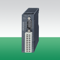
FM 250 - Counter module 2/4 channels with 32/16 Bit DC 24 V or via backplane bus Free configurable DC 24 V outputs (1 A) Up to 1 MHz |
|
|
250-1BS00 |
FM 250S - SSI module␍ 1 SSI channel Direct power supply to the SSI transducer Baud rate: 100/300/600 kBit/s (default: 300 kBit/s) 2 configurable digital outputs, one may be used as hold input |
|
|
253-1BA00 |
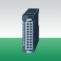
FM 253 - Positioning module␍ Positioning module for 1axis drive with stepper 3 inputs for connecting end switches and 2 outputs |
|
|
254-1BA00 |
FM 254 - Positioning module␍ Positioning module for 1axis drive with servo For drives with an analog set point interface (+/-10 V control voltage) 3 inputs for connecting end switches and 2 outputs |
|
Изделие: 253-1BA00
Модуль управления шаговым двигателем FM 253, 1 ось, интерфейс управления RS-422, 3 канала DI 24 В пост. тока, 2 канала DO 24 В/1 А пост. тока
Изделие: 254-1BA00
Модуль управления серводвигателем FM 254, 1 ось, входы для поворотного шифратора приращений (RS-422), 3 канала DI 24 В пост. тока, 2 канала DO 24 В/1 А пост. тока
Изделие: 250-1BA00
Счетный модуль FM 250, 2 счетчика (32 разряда) или 4 счетчика (16 разрядов), частота входных импульсов до 1 МГц, 2 канала DO 24 В/1 А пост. тока
г. Алматы, Ауэзовский район
ул. Толе Би 302, Литер "Д"
офис № 205
+7 (727) 268-0321
+7 (701) 082-9486
+7 (707) 493-7210
+7 (727) 268-0321
info@controllink.kz