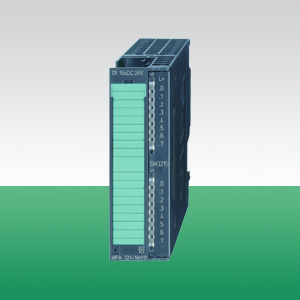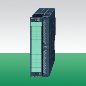
Модуль аналоговых входов-выходов AI4x12Bit, U/I/R, AO2x 0…10 V
|
Наименование
|
SM 334 |
|
Тип
|
334-0KE00 |
|
Описание
|
Используется в системах VIPA 300S, для подключения датчиков с аналоговым сигналом, а также для вывода аналоговых сигналов на управляющие механизмы. |
|
Габаритные размеры,
В х Ш х Г, мм
|
40 mm x 125 mm x 120 mm |
|
Сайт производителя
|
www.vipa.de |
|
Монтаж
|
Профильная рейка 390-xxxx |
|
Температура окружающей среды
|
0 °C .. 60 °C |
|
Серия
|
300S |
|
Количество входов
|
4 |
|
Количество выходов
|
2 |
|
Тип входного сигнала
|
U/I/R |
|
Тип выходного сигнала
|
U/I |
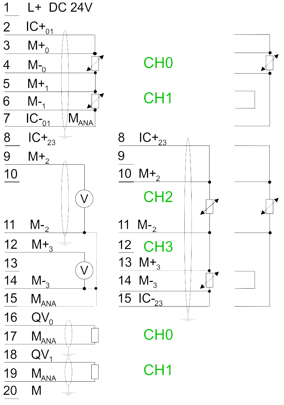
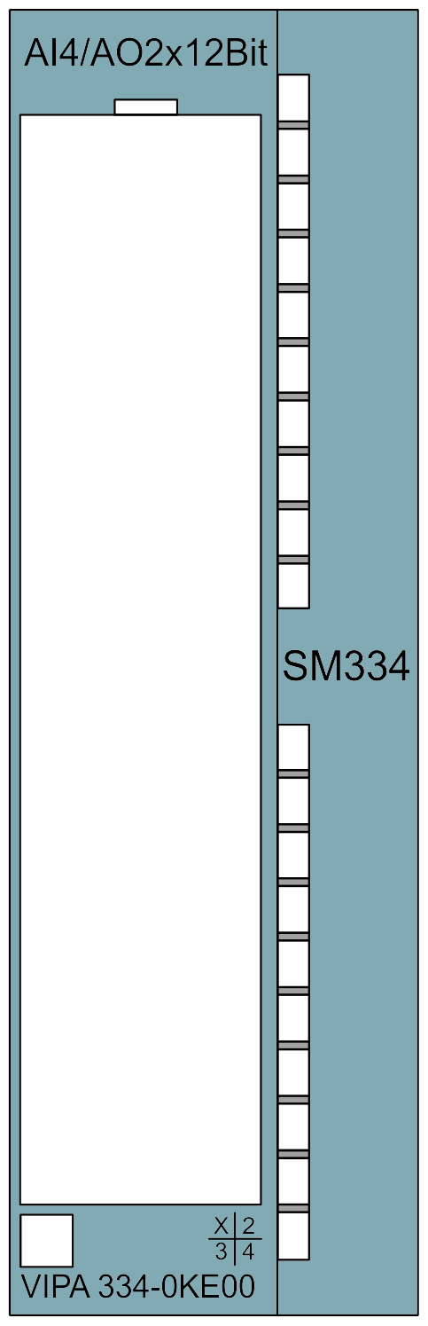
Pin assignment Circuit diagram Status monitor
|
Connection |
334-0KE00 |
 |
 |
 |
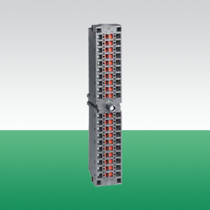
Фронтальный соединитель для модулей серии 300S392-1AJ00 20 контактов с винтовыми клеммами |
| |
Фронтальный соединитель для модулей серии 300S392-1BJ00 20 контактов с пружинными клеммами |
 |
Фронтальный соединитель922-3BC50 20 контактов с винтовыми клеммами, смонтированный жгут изолированных проводов сечением 0,5 кв. мм и длиной 2,5 м |
| |
Фронтальный соединитель922-3BD20 20 контактов с винтовыми клеммами, смонтированный жгут изолированных проводов сечением 0,5 кв. мм и длиной 3,2 м |
|
Фронтальный соединитель922-3BF00 20 контактов с винтовыми клеммами, смонтированный жгут изолированных проводов сечением 0,5 кв. мм и длиной 5 м |
Order no. |
334-0KE00 |
| Type | SM 334 |
General information |
|
| Note | - |
| Features | 4 inputs, 2 outputs Configurable Resistance Voltage 0...10 V |
| SPEED-Bus | - |
Current consumption/power loss |
|
| Current consumption from backplane bus | 95 mA |
| Power loss | 2 W |
Technical data analog inputs |
|
| Number of inputs | 4 |
| Cable length, shielded | 100 m |
| Rated load voltage | DC 24 V |
| Reverse polarity protection of rated load voltage | - |
| Current consumption from load voltage L+ (without load) | 40 mA |
| Voltage inputs |  |
| Min. input resistance (voltage range) | 100 kΩ |
| Input voltage ranges | 0 V ... +10 V |
| Operational limit of voltage ranges | +/-0.7% |
| Operational limit of voltage ranges with SFU | - |
| Basic error limit voltage ranges | +/-0.5% |
| Basic error limit voltage ranges with SFU | - |
| Destruction limit current | - |
| Current inputs | - |
| Max. input resistance (current range) | - |
| Input current ranges | - |
| Operational limit of current ranges | - |
| Operational limit of current ranges with SFU | - |
| Basic error limit current ranges | - |
| Radical error limit current ranges with SFU | - |
| Destruction limit current inputs (electrical current) | - |
| Destruction limit current inputs (voltage) | - |
| Resistance inputs | |
| Resistance ranges | 10000 Ohm |
| Operational limit of resistor ranges | +/-3.5% |
| Operational limit of resistor ranges with SFU | - |
| Basic error limit | +/-2.8% |
| Basic error limit with SFU | - |
| Destruction limit resistance inputs | - |
| Resistance thermometer inputs | |
| Resistance thermometer ranges | Pt100 |
| Operational limit of resistance thermometer ranges | +/-0.1% |
| Operational limit of resistance thermometer ranges with SFU | - |
| Basic error limit thermoresistor ranges | +/-0.8% |
| Basic error limit thermoresistor ranges with SFU | - |
| Destruction limit resistance thermometer inputs | - |
| Thermocouple inputs | - |
| Thermocouple ranges | - |
| Operational limit of thermocouple ranges | - |
| Operational limit of thermocouple ranges with SFU | - |
| Basic error limit thermoelement ranges | - |
| Basic error limit thermoelement ranges with SFU | - |
| Destruction limit thermocouple inputs | - |
| Programmable temperature compensation | - |
| External temperature compensation | - |
| Internal temperature compensation | - |
| Internal temperature compensation | - |
| Technical unit of temperature measurement | - |
| Resolution in bit | 12 |
| Measurement principle | Sigma-Delta |
| Basic conversion time | 350 ms |
| Noise suppression for frequency | 50 Hz/60 Hz |
| Initial data size | 8 Byte |
Technical data analog outputs |
|
| Number of outputs | 2 |
| Cable length, shielded | 100 m |
| Rated load voltage | DC 24 V |
| Reverse polarity protection of rated load voltage | |
| Current consumption from load voltage L+ (without load) | 40 mA |
| Voltage output short-circuit protection | |
| Voltage outputs | |
| Min. load resistance (voltage range) | 1 kΩ |
| Max. capacitive load (current range) | 1 µF |
| Max. inductive load (current range) | 25 mA |
| Output voltage ranges | 0 V ... +10 V |
| Operational limit of voltage ranges | +/-1% |
| Basic error limit voltage ranges | +/-0.8% |
| Destruction limit against external applied voltage | - |
| Current outputs | - |
| Max. in load resistance (current range) | - |
| Max. inductive load (current range) | - |
| Max. inductive load (current range) | - |
| Output current ranges | - |
| Operational limit of current ranges | - |
| Basic error limit current ranges | - |
| Destruction limit against external applied voltage | - |
| Settling time for ohmic load | 0.8 ms |
| Settling time for capacitive load | 0.8 ms |
| Settling time for inductive load | 0.3 ms |
| Resolution in bit | 12 |
| Conversion time | 0.5 ms per channel |
| Substitute value can be applied | - |
| Output data size | 4 Byte |
Status information, alarms, diagnostics |
|
| Status display | none |
| Interrupts | no |
| Process alarm | no |
| Diagnostic interrupt | no |
| Diagnostic functions | no |
| Diagnostics information read-out | none |
| Supply voltage display | none |
| Group error display | none |
| Channel error display | none |
Isolation |
|
| Between channels | - |
| Between channels of groups to | - |
| Between channels and backplane bus | |
| Between channels and power supply | |
| Max. potential difference between circuits | - |
| Max. potential difference between inputs (Ucm) | DC 1 V |
| Max. potential difference between Mana and Mintern (Uiso) | DC 75 V/ AC 60 V |
| Max. potential difference between inputs and Mana (Ucm) | DC 1 V |
| Max. potential difference between inputs and Mintern (Uiso) | - |
| Max. potential difference between Mintern and outputs | - |
| Insulation tested with | DC 500 V |
Datasizes |
|
| Input bytes | 8 |
| Output bytes | 4 |
| Parameter bytes | 21 |
| Diagnostic bytes | 0 |
Housing |
|
| Material | PPE |
| Mounting | Rail System 300 |
Mechanical data |
|
| Dimensions (WxHxD) | 40 mm x 125 mm x 120 mm |
| Weight | 210 g |
Environmental conditions |
|
| Operating temperature | 0 °C to 60 °C |
| Storage temperature | -25 °C to 70 °C |
Certifications |
|
| UL508 certification | yes |
| Order no. | Name/Description | |
|---|---|---|
|
331-1KF01 |
SM 331 - Analog input␍ 8 inputs 13 bit Voltage, current Resistance Resistance thermometer |
|
|
331-7AF70 |
SM 331S - Analog input FAST - SPEED-Bus␍ 8 inputs Current ±20 mA Oscilloscope-/FIFO function Interrupt parameterizable |
|
|
331-7BF70 |
SM 331S - Analog input FAST - SPEED-Bus 8 inputs Voltage ±10 V Oscilloscope-/FIFO-Function Interrupt parameterizable |
|
|
331-7KB01 |
SM 331 - Analog input␍ 2 inputs, in 1 group Voltage, current Resistance Resistance thermometer Thermocouples |
|
|
331-7KF01 |
SM 331 - Analog input␍ 8 inputs, in 4 groups Voltage, current Resistance Resitance thermometer Thermocouples |
|
|
332-5HB01 |
SM 332 - Analog output␍ 2 outputs Configurable Voltage, current |
|
|
332-5HD01 |
SM 332 - Analog output␍ 4 outputs Configurable Voltage, current |
|
|
334-0KE00 |
SM 334 - Analog in-/output 4 inputs, 2 outputs Configurable Resistance Voltage 0...10 V |
|
|
||||||||||||||||||||||||||||||||||||||||||||||||||||||||||||||||||||||||||||||||||||||||||||||||||||||||||||||||||||||||||||||||||||||||||||||||||||||||||||||||||||
г. Алматы, Ауэзовский район
ул. Толе Би 302, Литер "Д"
офис № 205
+7 (727) 268-0321
+7 (701) 082-9486
+7 (707) 493-7210
+7 (727) 268-0321
info@controllink.kz