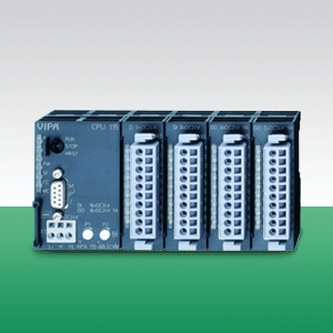
Модуль CPU 115, 16 (20) входов, 16 (12) выходов, 32 кбайт рабочей памяти, 40 кбайт загрузочной памяти, расширяемый, бесплатное ПО WinPLC7 Lite
|
Наименование
|
CPU 115 MicroPLC |
|
Тип
|
VIPA 115-6BL04 |
|
Габаритные размеры, В х Ш х Г, мм
|
152.4 mm x 76 mm x 48 mm |
|
Температура окружающей среды
|
0 °C .. 60 °C |
|
Серия
|
100V |
|
Поддерживаемые протоколы
|
MPI |
|
Объем памяти
|
32 КБ |
|
Количество сигналов
|
DI 16(20)xDC 24В/ DO 16(12)xDC 24В |
 |
|
LEDs
| Label | Color | Description |
| R | green | CPU is in the operating mode RUN. |
| S | yellow | CPU is in the operating mode STOP. |
| PW | green | Signalizes the started CPU. |
| SF | red | Blinks at system errors (hardware defect) |
| FC | yellow | Blinks, if variables are forced (fixed). |
| MC | yellow |
Blinking shows accesses at the MMC. |
Interface
| MP2I | Description | |
 |
|
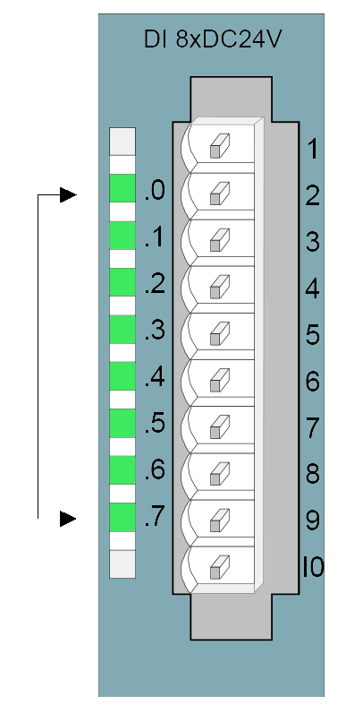
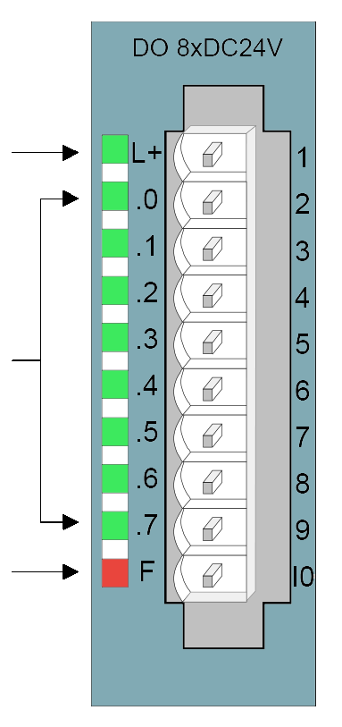
Status monitor pin assignment
| LED | Description | Pin assignment | |||
| .0... .7 |
LEDs (green) |
 |
|
*) At X3 parameterizable as counter res. alarm input.
| LED | Description | Pin assignment | |||
| L+ |
LED (green) |
 |
|
||
| .0... .7 |
LEDs (green) |
||||
| F |
LED (red) |
*) At X5 parameterizable as pulse output with max. output current of 0.5A per channel.
Order no. |
115-6BL04 |
| Type | CPU 115 |
General information |
|
| Note | - |
| Features | 16 (20) inputs 16 (12) outputs from which are 2 PWM 50 kHz outputs 32 kB work memory, 40 kB load memory |
Technical data power supply |
|
| Power supply (rated value) | DC 24 V |
| Power supply (permitted range) | DC 20.4...28.8 V |
| Reverse polarity protection |  |
| Current consumption (no-load operation) | 90 mA |
| Current consumption (rated value) | 1 A |
| Inrush current | 58 A |
| I²t | 0.38 A²s |
| Max. current drain at backplane bus | 0.8 A |
| Power loss | 8.5 W |
| Reverse polarity protection | |
Technical data digital inputs |
|
| Number of inputs | 16 (20 |
| Cable length, shielded | 1000 m |
| Cable length, unshielded | 600 m |
| Rated load voltage | DC 24 V |
| Reverse polarity protection of rated load voltage | |
| Current consumption from load voltage L+ (without load) | - |
| Rated value | DC 24 V |
| Input voltage for signal "0" | DC 0...5 V |
| Input voltage for signal "1" | DC 15...28.8 V |
| Input current for signal "1" | 7 mA |
| Connection of Two-Wire-BEROs possible | |
| Max. permissible BERO quiescent current | 1.5 mA |
| Input delay of "0" to "1" | 3 ms |
| Input delay of "1" to "0" | 3 ms |
| Input characteristic curve | IEC 61131-2, type 1 |
| Initial data size | 3 Byte |
Technical data digital outputs |
|
| Number of outputs | 16 (12 |
| Cable length, shielded | 1000 m |
| Cable length, unshielded | 600 m |
| Rated load voltage | DC 24 V |
| Reverse polarity protection of rated load voltage | - |
| Current consumption from load voltage L+ (without load) | 50 mA |
| Total current per group, horizontal configuration, 40°C | 4 A |
| Total current per group, horizontal configuration, 60°C | 4 A |
| Total current per group, vertical configuration | 4 A |
| Output voltage signal "1" at min. current | L+ (-125 mV) |
| Output voltage signal "1" at max. current | L+ (-0.8 V) |
| Output current at signal "1", rated value | 0.5 A |
| Output delay of "0" to "1" | max. 100 µs |
| Output delay of "1" to "0" | max. 350 µs |
| Minimum load current | - |
| Lamp load | 5 W |
| Switching frequency with resistive load | max. 1000 Hz |
| Switching frequency with inductive load | max. 0.5 Hz |
| Switching frequency on lamp load | max. 10 Hz |
| Internal limitation of inductive shut-off voltage | L+ (-52 V) |
| Short-circuit protection of output | yes, electronic |
| Trigger level | 1 A |
| Output data size | 3 Byte |
Technical data counters |
|
| Number of counters | 4 |
| Counter width | 32 Bit |
| Maximum input frequency | 30 kHz |
| Maximum count frequency | 30 kHz |
| Mode incremental encoder | |
| Mode pulse / direction | |
| Mode pulse | |
| Mode frequency counter | - |
| Mode period measurement | - |
| Gate input available | |
| Latch input available | - |
| Reset input available | - |
| Counter output available | - |
Status information, alarms, diagnostics |
|
| Status display | yes |
| Interrupts | yes |
| Process alarm | yes |
| Diagnostic interrupt | yes |
| Diagnostic functions | no |
| Diagnostics information read-out | possible |
| Supply voltage display | green LED |
| Group error display | red SF LED |
| Channel error display | none |
Isolation |
|
| Between channels of groups to | 8 |
| Between channels and backplane bus | |
| Insulation tested with | DC 500 V |
PWM data |
|
| PWM channels | 2 |
| PWM time basis | - |
| Period length | - |
| Minimum pulse width | - |
| PtP communication | - |
Technical data power supply |
|
| Power supply (rated value) | DC 24 V |
| Power supply (permitted range) | DC 20.4...28.8 V |
| Reverse polarity protection | |
| Current consumption (no-load operation) | 90 mA |
| Current consumption (rated value) | 1 A |
| Inrush current | 58 A |
| I²t | 0.38 A²s |
| Max. current drain at backplane bus | 0.8 A |
| Max. current drain load supply | - |
| Power loss | 8.5 W |
Load and working memory |
|
| Load memory, integrated | 40 KB |
| Load memory, maximum | 40 KB |
| Work memory, integrated | 32 KB |
| Work memory, maximal | 32 KB |
| Memory divided in 50% program / 50% data | - |
| Memory card slot | MMC-Card with max. 512 MB |
Hardware configuration |
|
| Racks, max. | 1 |
| Modules per rack, max. | 4 |
| Number of integrated DP master | - |
| Number of DP master via CP | 4 |
| Operable function modules | 4 |
| Operable communication modules PtP | 4 |
| Operable communication modules LAN | - |
Command processing times |
|
| Bit instructions, min. | 0.25 µs |
| Word instruction, min. | 1.2 µs |
| Double integer arithmetic, min. | 2.6 µs |
| Floating-point arithmetic, min. | 50 µs |
Timers/Counters and their retentive characteristics |
|
| Number of S7 counters | 256 |
| S7 counter remanence | adjustable 0 up to 64 |
| S7 counter remanence adjustable | C0 .. C7 |
| Number of S7 times | 256 |
| S7 times remanence | adjustable 0 up to 128 |
| S7 times remanence adjustable | not retentive |
Data range and retentive characteristic |
|
| Number of flags | 8192 Bit |
| Bit memories retentive characteristic adjustable | adjustable 0 up to 256 |
| Bit memories retentive characteristic preset | MB0 .. MB15 |
| Number of data blocks | 2047 |
| Max. data blocks size | 16 KB |
| Number range DBs | 1 ... 2047 |
| Max. local data size per execution level | 1024 Byte |
| Max. local data size per block | 1024 Byte |
Blocks |
|
| Number of OBs | 14 |
| Maximum OB size | 16 KB |
| Total number DBs, FBs, FCs | - |
| Number of FBs | 1024 |
| Maximum FB size | 16 KB |
| Number range FBs | 0 ... 1023 |
| Number of FCs | 1024 |
| Maximum FC size | 16 KB |
| Number range FCs | 0 ... 1023 |
| Maximum nesting depth per priority class | 8 |
| Maximum nesting depth additional within an error OB | 1 |
Time |
|
| Real-time clock buffered | |
| Clock buffered period (min.) | 30 d |
| Type of buffering | Vanadium Rechargeable Lithium Battery |
| Load time for 50% buffering period | 20 h |
| Load time for 100% buffering period | 48 h |
| Accuracy (max. deviation per day) | 10 s |
| Number of operating hours counter | 8 |
| Clock synchronization | - |
| Synchronization via MPI | - |
| Synchronization via Ethernet (NTP) | - |
Address areas (I/O) |
|
| Input I/O address area | 1024 Byte |
| Output I/O address area | 1024 Byte |
| Process image adjustable | - |
| Input process image preset | 128 Byte |
| Output process image preset | 128 Byte |
| Input process image maximal | 128 Byte |
| Output process image maximal | 128 Byte |
| Digital inputs | 8192 |
| Digital outputs | 8192 |
| Digital inputs central | 148 |
| Digital outputs central | 144 |
| Integrated digital inputs | 16 (20 |
| Integrated digital outputs | 16 (12 |
| Analog inputs | 512 |
| Analog outputs | 512 |
| Analog inputs, central | 32 |
| Analog outputs, central | 16 |
| Integrated analog inputs | - |
| Integrated analog outputs | - |
Communication functions |
|
| PG/OP channel | |
| Global data communication | |
| Number of GD circuits, max. | 4 |
| Size of GD packets, max. | 22 Byte |
| S7 basic communication | |
| S7 basic communication, user data per job | 76 Byte |
| S7 communication | |
| S7 communication as server | |
| S7 communication as client | - |
| S7 communication, user data per job | 160 Byte |
| Number of connections, max. | 16 |
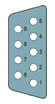
Functionality Sub-D interfaces |
|
| Type | MP²I |
| Type of interface | RS485 |
| Connector | Sub-D, 9-pin, female |
| Electrically isolated | - |
| MPI | |
| MP²I (MPI/RS232) | |
| Point-to-point interface | - |
Functionality MPI |
|
| Number of connections, max. | 16 |
| PG/OP channel | |
| Routing | - |
| Global data communication | |
| S7 basic communication | |
| S7 communication | |
| S7 communication as server | |
| S7 communication as client | - |
| Transmission speed, min. | 19.2 kbit/s |
| Transmission speed, max. | 187.5 kbit/s |
Housing |
|
| Material | PPE / PA 6.6 |
| Mounting | Profile rail 35 mm |
Mechanical data |
|
| Dimensions (WxHxD) | 152.4 mm x 76 mm x 48 mm |
| Weight | 292 g |
Environmental conditions |
|
| Operating temperature | 0 °C to 60 °C |
| Storage temperature | -25 °C to 70 °C |
Certifications |
|
| UL508 certification | yes |
| Order no. | Name/Description | |
|---|---|---|
|
112-4BH02 |
CPU 112 - Micro PLC 8 (12) inputs 8 (4) outputs 8 kB work memory, 16 kB load memory |
|
|
114-6BJ02 |
CPU 114 - Micro PLC 16 (20) inputs 8 (4) outputs from which are 2 PWM 50 kHz outputs 16 kB work memory, 24 kB load memory |
|
|
114-6BJ03 |
CPU 114 - Micro PLC 16 (20) inputs 8 (4) outputs from which are 2 PWM 50 kHz outputs 24 kB work memory, 32 kB load memory |
|
|
114-6BJ04 |
CPU 114 - Micro PLC 16 (20) inputs 8 (4) outputs from which are 2 PWM 50 kHz outputs 32 kB work memory, 40 kB load memory |
|
|
114-6BJ52 |
CPU 114R - Micro PLC 16 inputs 8 relay outputs AC 230 V/ DC 30 V 16 kB work memory, 24 kB load memory |
|
|
114-6BJ53 |
CPU 114R - Micro PLC 16 inputs 8 relay outputs AC 230 V/ DC 30 V 24 kB work memory, 32 kB load memory |
|
|
114-6BJ54 |
CPU 114R - Micro PLC 16 inputs 8 relay outputs AC 230 V/ DC 30 V 32 kB work memory, 40 kB load memory |
|
|
115-6BL02 |
CPU 115 - Micro PLC 16 (20) inputs 16 (12) outputs from which are 2 PWM 50 kHz outputs 16 kB work memory, 24 kB load memory |
|
|
115-6BL03 |
CPU 115 - Micro PLC 16 (20) inputs 16 (12) outputs from which are 2 PWM 50 kHz outputs 24 kB work memory, 32 kB load memory |
|
|
115-6BL04 |
CPU 115 - Micro PLC 16 (20) inputs 16 (12) outputs from which are 2 PWM 50 kHz outputs 32 kB work memory, 40 kB load memory |
|
|
115-6BL12 |
CPU 115SER - Micro PLC 16 (20) inputs 16 (12) outputs from which are 2 PWM 50 kHz outputs 16 kB work memory, 24 kB load memory RS232 interface |
|
|
115-6BL13 |
CPU 115SER - Micro PLC 16 (20) inputs 16 (12) outputs from which are 2 PWM 50 kHz outputs 24 kB work memory, 32 kB load memory RS232 interface |
|
|
115-6BL14 |
CPU 115SER - Micro PLC 16 (20) inputs 16 (12) outputs from which are 2 PWM 50 kHz outputs 32 kB work memory, 40 kB load memory RS232 interface |
|
|
115-6BL22 |
CPU 115DP - Micro PLC 16 (20) inputs 16 (12) outputs 16 kB work memory, 24 kB load memory PROFIBUS-DP slave interface |
|
|
115-6BL23 |
CPU 115DP - Micro PLC 16 (20) inputs 16 (12) outputs from which are 2 PWM 50 kHz outputs 24 kB work memory, 32 kB load memory PROFIBUS-DP slave interface |
|
|
115-6BL24 |
CPU 115DP - Micro PLC 16 (20) inputs 16 (12) outputs 32 kB work memory, 40 kB load memory PROFIBUS-DP slave interface |
|
|
115-6BL32 |
CPU 115SER - Micro PLC 16 (20) inputs 16 (12) outputs from which are 2 PWM 50 kHz outputs 16 kB work memory, 24 kB load memory RS485 interface |
|
|
115-6BL33 |
CPU 115SER - Micro PLC 16 (20) inputs 16 (12) outputs from which are 2 PWM 50 kHz outputs 24 kB work memory, 32 kB load memory RS485 interface |
|
|
115-6BL34 |
CPU 115SER - Micro PLC 16 (20) inputs 16 (12) outputs from which are 2 PWM 50 kHz outputs 32 kB work memory, 40 kB load memory RS485 interface |
|
Изделие: 115-6BL34
16 (20) входов, 16 (12) выходов, 32 кбайт рабочей памяти, 40 кбайт загрузочной памяти, 2-й интерфейс RS-485 (PtP), расширяемый

Изделие: 114-6BJ52
16 входов, 8 релейных выходов (230 В перем. тока/30 В пост. тока), 16 кбайт рабочей памяти, 24 кбайт загрузочной памяти, расширяемый
Изделие: 115-6BL33
16 (20) входов, 16 (12) выходов, 24 кбайт рабочей памяти, 32 кбайт загрузочной памяти, 2-й интерфейс RS-485 (PtP), расширяемый

Изделие: 114-6BJ04
16 (20) входов, 8 (4) выходов, 32 кбайт рабочей памяти, 40 кбайт загрузочной памяти, расширяемый
г. Алматы, Ауэзовский район
ул. Толе Би 302, Литер "Д"
офис № 205
+7 (727) 268-0321
+7 (701) 082-9486
+7 (707) 493-7210
+7 (727) 268-0321
info@controllink.kz